How Rendering Makes an Image
A rendered image is the numerical estimate of radiance recorded at a finite set of image samples; although the result is conventionally described as a picture, the renderer itself constructs an array of linear color values that is only later transformed into something suitable for a display device. Thinking in terms of “drawing objects” therefore obscures the actual problem, because geometry, materials, and lights are merely the data from which the renderer estimates the radiance associated with each pixel footprint.
A pixel is not a point in the scene, nor is it necessarily associated with one surface. It represents a small region of the sensor or image plane, and its value may depend on visibility across that region, the aperture of the lens, the time at which the shutter was sampled, and the spectrum or wavelength range being represented. Rendering is consequently a sampling problem before it is a shading problem.
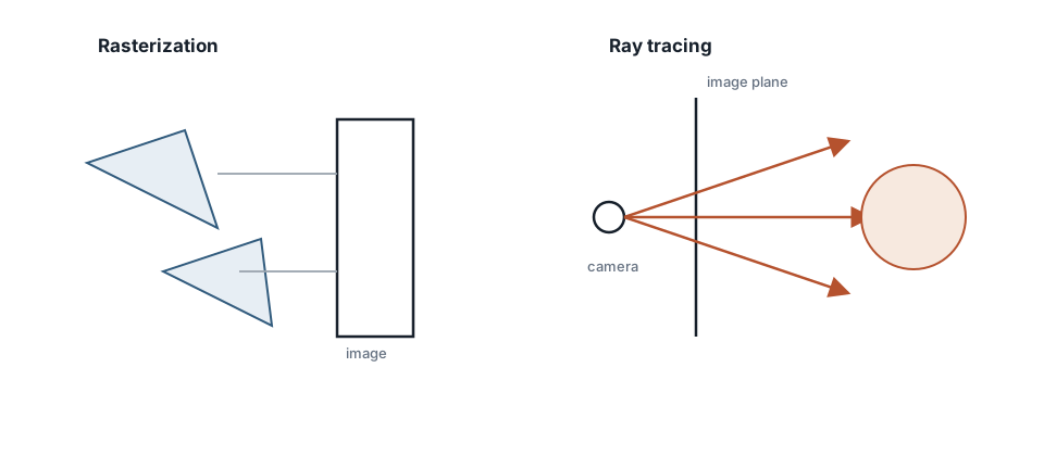
Rasterization projects primitives toward image samples, whereas ray tracing begins at an image sample and queries the scene for the first visible surface.
The two questions associated with every image sample
Every rendering pipeline must answer two related but distinct questions. First, it must establish visibility: which surface, if any, is visible through the particular image sample under consideration? Second, once that surface has been identified, it must perform shading: how much radiance leaves the surface in the direction of the camera?
The separation is not merely conceptual. No material model can repair an incorrect nearest-surface decision, and a perfectly correct intersection system will still produce an unconvincing image if the outgoing radiance is evaluated incorrectly. A ray tracer resolves primary visibility by tracing a camera ray and retaining the nearest valid intersection, while a rasterizer resolves it by projecting primitives, generating fragments, and applying a depth comparison. In either case, the visibility stage ultimately delivers the same useful information: a surface position, a normal, material parameters, and a direction toward the observer.
Rasterization and ray tracing
Rasterization is conventionally described as an object-to-image algorithm. Triangles are transformed, clipped, projected, and rasterized into covered samples, after which depth testing selects the visible fragment. The regularity of this workload is one reason modern GPUs execute primary visibility so efficiently.
Ray tracing instead begins with image samples. A camera ray passes through the selected image location and asks which scene primitive it intersects first. This formulation makes secondary visibility, including shadows, reflections, and refractions, structurally natural because each effect is another ray query; its cost is that an unaccelerated implementation would test each ray against every primitive in the scene. The visibility algorithm and the shading model are independent choices, so a ray tracer may render a stylized material and a rasterizer may render a physically based one. Production renderers commonly combine both approaches.
Linear radiance and display encoding
All transport calculations belong in linear floating-point space, where halving a radiance value halves the stored number and addition corresponds to the physical accumulation being approximated. Display encodings such as sRGB are designed for storage and presentation, not for intermediate lighting arithmetic. Applying lighting operations to display-encoded values changes the mathematics of interpolation, blending, and energy accumulation, which is why it produces implausible dark transitions and unstable material response.
A minimal image-formation pipeline is therefore:
scene description
  -> camera sample
  -> visibility query
  -> surface shading
  -> accumulate in a linear buffer
  -> divide by sample count
  -> exposure and tone mapping
  -> sRGB encoding
  -> image file or display
The distinction between the linear accumulation buffer and the display image should remain explicit in the architecture. Tone mapping is an output transform, not a lighting operation, and applying it while samples are still accumulating biases the estimate.
Geometric conventions
Before any intersection routine is implemented, the coordinate conventions of the renderer should be specified in one place and treated as part of the mathematical model:
- whether the camera looks along positive or negative Z,
- whether the scene uses Y-up or Z-up coordinates,
- whether vectors multiply matrices as rows or columns,
- which triangle winding denotes a front face, and
- the valid ray interval $[t_{\min}, t_{\max}]$.
No particular convention is inherently preferable, but mixing conventions is catastrophic because the resulting failures resemble unrelated bugs: mirrored images, inverted normals, and rays that appear to propagate backward. Primary rays normally exclude the exact origin by using a small positive lower bound; shadow rays must terminate before reaching the sampled light; and reflected or refracted rays begin slightly displaced from the source surface to avoid self-intersection.
First exercise
Implement a constant-background scene containing one sphere, then color each hit by remapping its unit normal from $[-1,1]$ to $[0,1]$. Add a plane and a second overlapping object, and vary the camera rather than moving the geometry to compensate for an incorrect view. When nearer surfaces consistently win and the normal visualization remains coherent under camera motion, the camera basis and nearest-hit selection are credible enough to support lighting.
Common errors
- treating the pixel center as if it represented the entire pixel footprint,
- performing lighting calculations in display-encoded color values,
- confusing ray tracing with a material or lighting model,
- accepting intersections behind the ray origin or beyond a sampled light, and
- adding sophisticated BRDFs before the visibility path has been validated.
The rest of the series refines individual stages of this chain, but none of those refinements can compensate for a confused model of how a rendered image is formed.